


Advantage
Fine-Fin® provides 2.5 to 3 times the external surface area of bare tube
This yields numerous benefits for the heat transfer equipment
Reduced capital cost for new equipment
Enhanced heat exchange efficiency means less Fine-Fin tubing is required to accomplish the same heat transfer as a bare tube.
Reduced retrofitting cost for existing equipment
Fine-Fin can increase the performance of an existing heat exchanger without the difficult and expensive task of building new shells, heads, nozzles, piping and foundations.
Space, weight & structural savings
Reduced plot space and weight can be extremely valuable in offshore production or high elevation distillation columns. Fine-Fin technology transforms large shell & tube exchangers into compact heat exchangers.
More materials & alloys to select
Fine-Fin is available in a wider range of alloys than traditional low-fin tubing which is restricted to soft metals. This opens a new world of opportunity for enhanced tubing in corrosive service. The more expensive the tube material, the more dramatic the cost savings of Fine-Fin.
Reduced maintenance & life cycle cost
Proper material selection with Fine-Fin can eliminate costly downtime & maintenance. Example: Coastal refineries using once-through seawater cooling systems can benefit by substituting conventional copper nickel tubing with Titanium Fine-Fin tubing. Titanium Fine-Fin is highly resistant to seawater corrosion erosion.
Application
The Integral low fin tubes are widely used in chemicalprocess. Especially applicable between air or other gases on the fin-side and a fluid on the tube-side.| 28 FPI 0.889mm average fin height 0.305mm average fin thickness | ||||||||||
| No. | Plain Section avg. OD | Plain section avg. wall | Wall Under fin avg | Wall Under Fin Min. | Nominal Root OD |
Fin Section ID |
Outside Area Ao |
Inside Area Ai |
Area Ratio Ao/Ai | ID cross Section Area |
| 153528 | 15.88 | 1.473 | 0.889 | 0.787 | 14.097 | 12.319 | 0.126 | 0.039 | 3.252 | 1.192 |
| 154228 | 15.88 | 1.651 | 1.067 | 0.940 | 14.097 | 11.963 | 0.126 | 0.037 | 3.358 | 1.124 |
| 192828 | 19.05 | 1.245 | 0.711 | 0.635 | 17.272 | 15.85- | 0.153 | 0.050 | 3.074 | 1.973 |
| 193528 | 19.05 | 1.473 | 0.889 | 0.787 | 17.272 | 15.494 | 0.153 | 0.049 | 3.131 | 0.292 |
| 194228 | 19.05 | 1.651 | 1.067 | 0.940 | 17.272 | 15.138 | 0.153 | 0.048 | 3.212 | 1.800 |
| 253528 | 25.40 | 1.473 | 0.889 | 0.787 | 24.622 | 21.844 | 0.206 | 0.069 | 3.004 | 3.748 |
| 253528 | 25.40 | 1.651 | 1.067 | 0.940 | 24.622 | 21.488 | 0.206 | 0.067 | 3.059 | 3.627 |
| 30 FPI 0.813mm average fin height 0.279mm average fin thickness | ||||||||||
| No. | Plain Section avg. OD | Plain section avg. wall | Wall Under Fin avg. | Wall Under Fin Min. | Nominal Root OD |
Fin Section ID |
Outside Area Ao |
Inside Area Ai |
Area Ratio Ao/Ai | ID cross Section Area |
| 153530 | 15.88 | 1.473 | 0.889 | 0.787 | 14.249 | 12.471 | 0.125 | 0.039 | 3.186 | 1.222 |
| 154230 | 15.88 | 1.651 | 1.067 | 0.940 | 14.249 | 12.116 | 0.125 | 0.038 | 3.288 | 1.153 |
| 192830 | 19.05 | 1.245 | 0.711 | 0.635 | 17.424 | 16.002 | 0.152 | 0.050 | 3.030 | 2.011 |
| 193530 | 19.05 | 1.473 | 0.889 | 0.787 | 17.424 | 15.646 | 0.152 | 0.049 | 3.106 | 1.923 |
| 194230 | 19.05 | 1.651 | 1.067 | 0.940 | 17.424 | 15.291 | 0.152 | 0.048 | 3.165 | 1.836 |
| 253530 | 25.40 | 1.473 | 0.889 | 0.787 | 23.774 | 21.996 | 0.205 | 0.069 | 2.956 | 3.800 |
| 253530 | 25.40 | 1.651 | 1.067 | 0.940 | 23.774 | 21.641 | 0.205 | 0.068 | 3.009 | 3.678 |
| 36 FPI 0.66mm average fin height 0.305mm average fin thickness | ||||||||||
| No. | Plain Section avg. OD | Plain section avg. wall | Wall Under Fin avg. | Wall Under Fin Min. | Nominal Root OD |
Fin Section ID |
Outside Area Ao |
Inside Area Ai |
Area Ratio Ao/Ai | ID cross Section Area |
| 153536 | 15.88 | 1.473 | 0.889 | 0.787 | 14.554 | 12.776 | 0.125 | 0.040 | 3.114 | 1.282 |
| 154236 | 15.88 | 1.651 | 1.067 | 0.940 | 14.554 | 12.421 | 0.125 | 0.039 | 3.211 | 1.212 |
| 192836 | 19.05 | 1.245 | 0.711 | 0.635 | 17.729 | 16.307 | 0.152 | 0.051 | 2.976 | 2.088 |
| 193536 | 19.05 | 1.473 | 0.889 | 0.787 | 17.729 | 15.951 | 0.152 | 0.050 | 3.049 | 1.998 |
| 194236 | 19.05 | 1.651 | 1.067 | 0.940 | 17.729 | 15.596 | 0.152 | 0.049 | 3.106 | 1.910 |
| 253536 | 25.40 | 1.473 | 0.889 | 0.787 | 24.079 | 22.301 | 0.205 | 0.070 | 2.917 | 3.906 |
| 253536 | 25.40 | 1.651 | 1.067 | 0.940 | 24.079 | 21.946 | 0.205 | 0.069 | 2.969 | 3.783 |
| 28 FPI 0.89 average fin height 0.305mm average fin thickness 0.254 average rib height | ||||||||||
| No. | Plain Section avg. OD | Plain section avg. wall | Wall Under Fin avg. | Wall Under Fin Min. | Nominal Root OD |
Fin Section ID |
Outside Area Ao |
Inside Area AI |
Area Ratio Ao/Ai | ID cross Section Area |
| 192828-201046 | 19.05 | 1.245 | 0.711 | 0.635 | 17.272 | 15.850 | 0.153 | 0.059 | 2.569 | 1.961 |
| 193528-201046 | 19.05 | 1.473 | 0.889 | 0.787 | 17.272 | 15.494 | 0.153 | 0.058 | 2.623 | 1.871 |
| 36 FPI 0.66 average fin height 0.305mm average fin thickness 0.254 average rib height | ||||||||||
| No. | Plain Section avg. OD | Plain section wall | Wall Under Fin avg. | Wall Under Fin Min. | Nominal Root OD |
Fin Section ID |
Outside Area Ao |
Inside Area AI |
Area Ratio Ao/Ai | ID cross Section Area |
| 192536-201046 | 19.05 | 1.245avg. | 0.635 | 0.559 | 17.729 | 16.459 | 0.152 | 0.062 | 2.463 | 2.116 |
| 192836-201046 | 19.05 | 1.245 min | 0.711 | 0.635 | 17.729 | 16.307 | 0.152 | 0.061 | 2.488 | 2.007 |
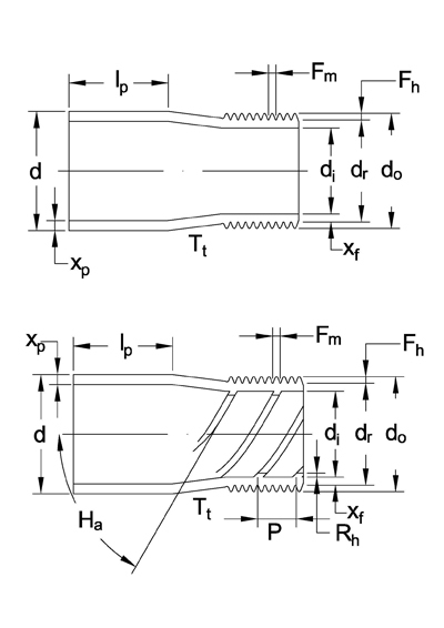 |
d= outside diameter of plain end di= inside diameter of plain end dr= root diameter do=diameter over fins di= inside diameter of fin section Xp=wall thickness of plain end Xf=wall thickness under fin Fh=height of fin Fm=fin thickness P=rib pitch Rh=height of rib Ha=helix angle |